The Internet of Things (IOT) is a great combination of Internet and things. If we use these things in a brilliant ways it will help human kind to make a better future. Internet of things is a modern system that uses devices those are particularly used to receive information and data from servers. After receiving data these devices do calculation and process it in the desired ways .In this article of series internet of things I am introducing an idea to make your androids devices to control hardware.
Check the first article in this Internet of Things series Here
Android is used in many devices in these days from smart phones to other devices. An android based Smartphone that have android installed in it can be used for controlling the Arduino Robot . This control takes place via Bluetooth and a user interface app. This app is used for interfacing with the Arduino UNO board.
Arduino UNO is the basic idea behind the scene. It is used as the controller for making the Android Bluetooth Controlled Arduino Robot or hardware.
Android Device
An android OS based Smartphone is used for controlling the Arduino Robot. Android OS must have Bluetooth connectivity and an Android User Interface app.
Controller:
Arduino UNO is a controller for making possible the Android Bluetooth Controlled Arduino Robot.
Bluetooth Module:
A Bluetooth module is just like remote control and is used for interfacing the Arduino Robot with the Android Smartphone wirelessly.
Motor Driver:
Arduino Robot use electrical motors, a motor driver IC – L293D Push-Pull Four Channel Driver IC- is used for controlling operations.
DC Motors for Robot:
The DC motors are used to move robot. The movement of the Arduino Robot is always depends upon the input given by the user.
How to make arduino board
It is easy to make arduino board from cheap electronic components.
Hardware we need for this project:
- An arduino bootloader ATmega328/168 or any compatible Atmel IC. Or a blank ATmega328, ATmega168 , ATmega 8 IC or any other compatible Atmel chips.
- LM7805 IC.
- 16 Mhz crystal.
- Tactile button.
- Led’s.
- Capacitors – 22pF (2 Nos), 10uF (2 Nos), 0.1uF (2 Nos).
- Resistors – 220Ohm (2 Nos), 1k (2 Nos).
- Pin headers (Male).
- 28 pin IC socket.
- Avr pocket programmer (Optional, only if uploading bootloader).
Software we need for this project:
- Arduino IDE : Arduino.
- Terminal for linux users and Command prompt for windows.
- Avrdude.
Other Tools we need for this project:
- Soldering iron.
- Solder lead.
- Prototyping solder dot board / breadboard or materials to etch your own board.
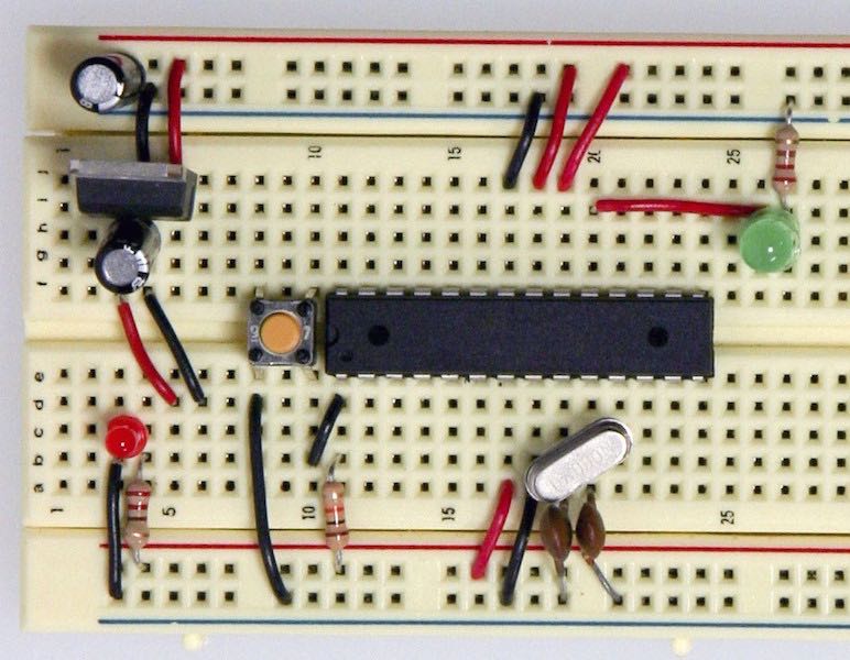
Put components together to make arduino board
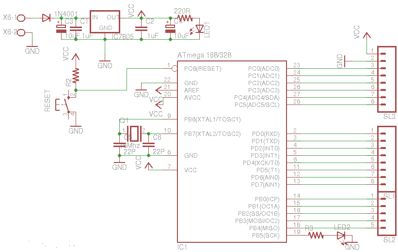
First collect each component at one place. Now connect these components with each other just like in the diagram below. A voltage regulator is used to filter the voltage. For clock we use a 16Mhz crystal along with its parallel connected 22pF capacitors. A led is connecting to pin no 19 of the ATmega .
Boot loader for ATmega chip
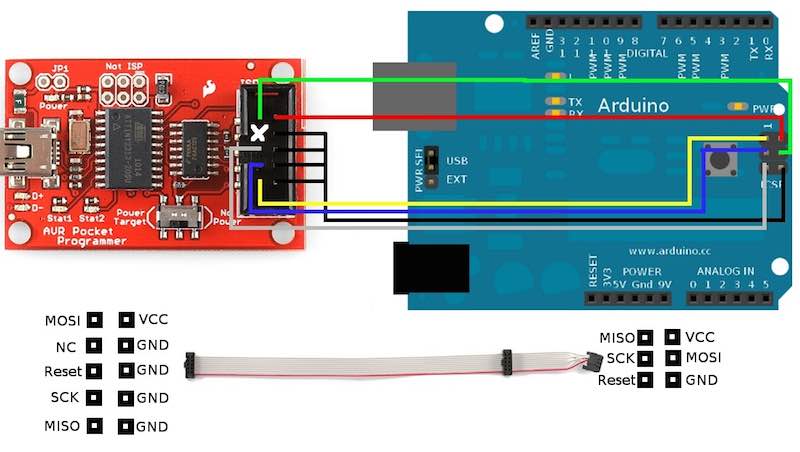
If you have a blank chip then you need this step. Others who already have an arduino bootloaded chip can ignore this step. An AVR pocket programmer can be used to burn the bootloader to various types of ATmega chips.
With an AVR Pocket Programer
Go to your installed arduino folder -> hardware -> arduino -> boards.txt. Then check the values of efuse, hfuse and lfuse. Now set the fuse bits for the blank chip. Open command prompt/terminal and paste the code below:
avrdude -b 19200 -c usbtiny -p m328p -v -e -U efuse:w:0x05:m -U hfuse:w:0xD6:m -U lfuse:w:0xFF:mNOTE: If you are using chips other than ATmega328 IC then substitute the values of efuse, hfuse and lfuse parameters after checking the boards.txt file and edit “m328p”.
Next, use the command below to upload the bootloader or your hex program file. Go to the path of your program file or bootloader (/hardware/arduino/bootloaders/atmega) from the command prompt/terminal and instead of “hexfilename.hex” substitute the name of your file.
avrdude -b19200 -c usbtiny -p m328p -v -e -U flash:w:hexfilename.hex -U lock:w:0x0F:mNow the file will be uploaded to ATmega chip successfully.
Using another arduino as ISP
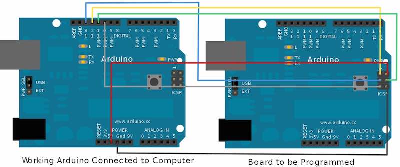
Another arduino is used for bootload the chip. It is must to have proper connections as per above diagram. You will also need two arduino boards for this: One will be a working arduino board and in the other one the blank ATmega chip needs to be inserted. Here we need to use ICSP (In Circuit Serial Programmer) pins of the arduino. Now start Arduio IDE after connecting working arduino to PC and go to tools->burn bootloader and in this section click on w/ Arduino as ISP. After these steps it should work properly if you have the correct chip specified in the boards.txt file but it works rarely. So I prefer the first method which is using AVR Pocket programmer.
Upload the code and use the board
Now use the Rx, Tx and Gnd pins to connect to a USB-UART TTL converter. This can be used for connecting with your PC.
In this method you can create your custom arduino board to perform any particular task and create an android app to show the interface to the user. Now you can use your android phone to control the board with bluetooth connectivity.

